| CMOS Design > Analog Cell Design |

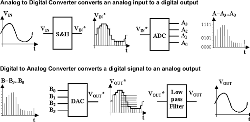
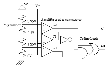
The analog-digital converter converts an analog value Vin into a two-bit digital value called A0,A1. The flash converter uses three converters and a coding logic to produce A0 and A1. A very complex logic circuit and 255 comparators would be used for an ADC eight-bit flash.
The polysilicon has a high resistance (50 per square) and can be used as a resistor network, which generates intermediate voltage references used by the voltage comparators located in the middle.
|

| Analog Input Vin |
C0 | C1 | C2 | A1 | A0 |
|---|---|---|---|---|---|
| Vin<1.25V | 0 | 0 | 0 | 0 | 0 |
| 1.25<Vin<2.5 | 1 | 0 | 0 | 0 | 1 |
| 2.5<Vin<3.5 | 1 | 1 | 0 | 1 | 0 |
| Vin>3.75V | 1 | 1 | 1 | 1 | 1 |
This digital-analog converter converts a digital three-bit input (A0,A1,A2) into an analog value Vout.
The polysilicon resistive net gives intermediate voltage references which flow to the output via a transmission gate net. The resistance symbol is inserted in the layout to indicate to the simulator that an equivalent resistance must be taken into account for the analog simulation.
|
| A2 | A1 | A0 | Analog output Vout (V) |
|---|---|---|---|
| 0 | 0 | 0 | 0.0 V |
| 0 | 0 | 1 | 0.625 |
| 0 | 1 | 0 | 1.25 |
| 0 | 1 | 1 | 1.875 |
| 1 | 0 | 0 | 2.5 |
| 1 | 0 | 1 | 3.125 |
| 1 | 1 | 0 | 3.75 |
| 1 | 1 | 1 | 4.375 |
| CMOS Design > Analog Cell Design > Converters |